
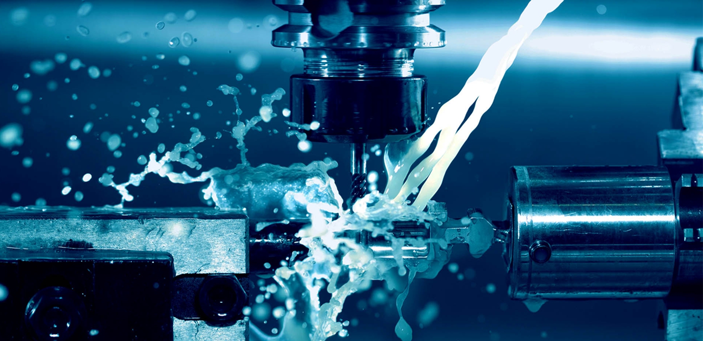
EXPERT IN PLASTIC INJECTION MOLD&MOLDING&PROTOTYPING
GALAXY3DM assists you in the design and manufacture of your parts and sub-assemblies in PUR materials. Our integrated offer of service in China provides you with a trusted collaboration with a single RIM engineering sub-contractor.
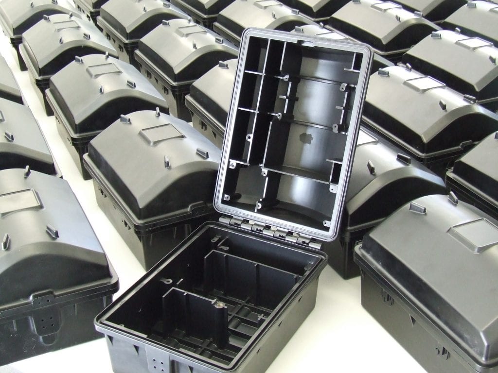
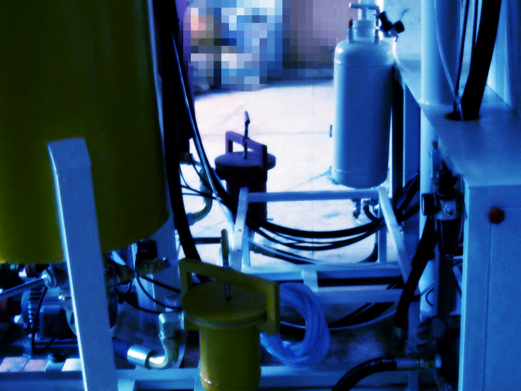

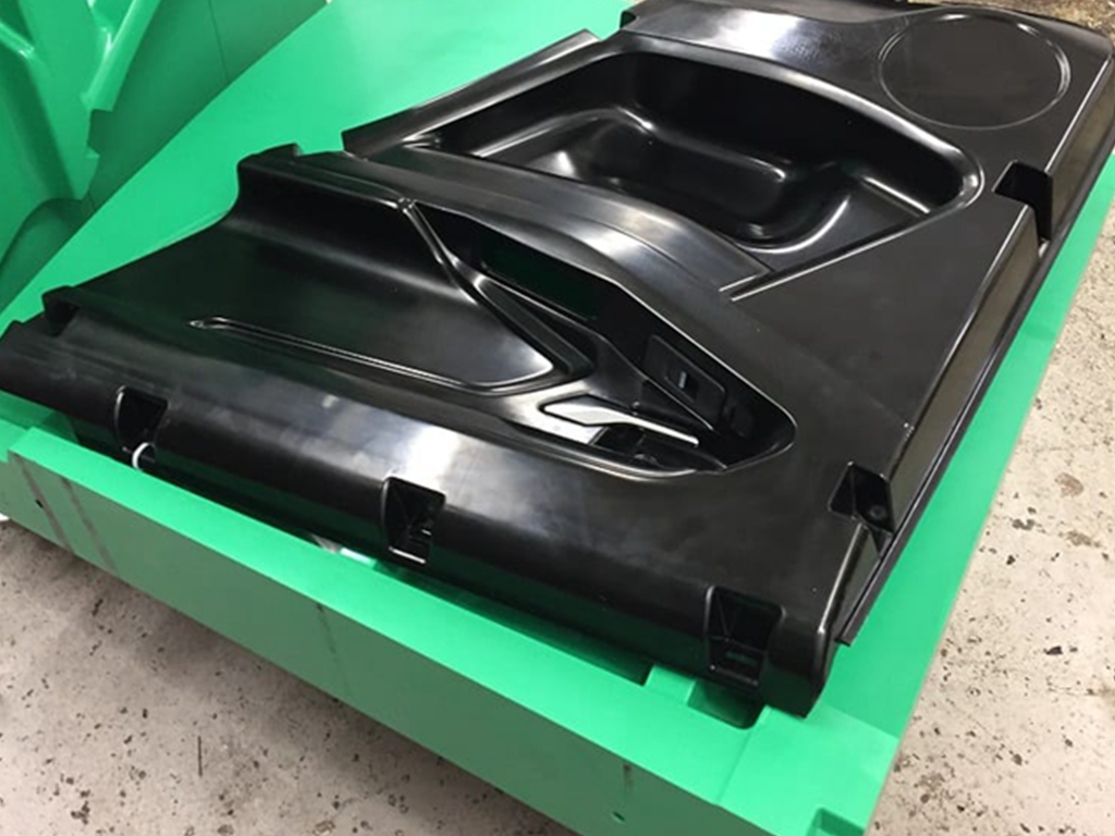
Both RIM Tooling and RIM Molding has special requirement about the experience of each RIM designer and each RIM performer.
Galaxy3DM design team has more than 10 years experience in RIM process field.
Our experienced engineers will select the best method for your project based on factors such as production volume, parts dimensions, budget, and other requirements.
Our extensive experience with RIM enables us to produce innovative and cost effective parts for our OEM customers.
RIM Molding Design Considerations
When considering RIM molding technology for your next low volume plastic enclosure, housing or assembly, there are many things to consider including, part size, part function, value added assembly, design for assembly techniques, molding in features, part cost, post mold assembly costs, tooling investment, part quality, repeatability and the ability for the tools and parts to retain quality, function and dimensional stability throughout the entire lifetime of the series production. Our design considerations will assist you to do that.
General RIM Molding Design Consideration

Functional Considerations
Environment the part will operate in
UV
Temperature
Humidity
Necessity for high impact resistance or stiffness
Parts loading conditions, attaching requirements, structural conditions
Chemical Resistance needed
Is Insert molding needed
Do you need a foamed system to cut down on part weight?

Economic Considerations
When making cost considerations, remember it’s the net shape of part that is important, not the weight. So make cost per volume calculation instead of cost per pound material decisions. Remember a 1" wall section in a foamed polyurethane will be much less than other materials systems including metals.
Look at the part geometry for load bearing applications.
Optimize wall thickness and rib ratios to reduce cost and weight.
Consider if the parts require paint.
General Part Design

Part Stiffness
Balance wall thickness and flexural modulus
Balance wall thickness and material density in foamed systems
Improve stiffness by adding glass (where possible)
Improve stiffness and reduce wall sections by using higher modulus systems, improving part geometry or adding reinforcements and encapsulations
Wall Thickness
Thicker Walls have higher stiffness
Double the wall thickness of a flat and the stiffness will increase by a factor of eight
Wall thickness can range from 1/8” up to 2” depending on the material system used and geometry
Thicker wall section require more cure time
Watch abnormally thick walls as they can cause dimensional stability issues due to longer cooling.
Rib Design and Configuration
Taller thinner ribs are more effective than shorter, wider ribs.
Run ribs continuously from side to side.
Design ribs in the direction of draw to minimize mold cost.
Draft
Every surface parallel to the direction of draw needs draft (1/2 a degree min) to facilitate demolding.
As the part height increases over 1”, draft should increase.
Add ¼” degree draft for each additional inch of draw over 1”.
Bosses
Attach bosses to the side walls of the part to allow air to escape during the molding process
Avoid isolated bosses
When design bosses that are not attached to a side wall, use gussets or vent the boss with a core
All bosses need radii at their bases
Holes, Grooves and Slots
Holes can be drilled in the part post mold, molded in the direction of draw or formed by a retractable pin using hydraulics in the tool.
Holes in side wall are also possible having the core and cavity meet at the hole.
Orient grooves and slots in the flow direction to minimize air entrapments.
Make sure grooves and slots are rounded or chamfered rather than sharp to help flow and vent air.
Consider positioning slots in a side wall curled around the base plane to allow for molding without slides.
Inserts
Minimum distance for the insert to the part wall should be 1/8 “ for a solid PUR or ¼” for a foamed system.
Metal, plastic, glass and electronics can be encapsulated in PUR materials
Threaded Inserts can be used if the parts are to be frequently disassembled by the end-user.
Threaded inserts can be either post mold or molded in the part
The insert design, hole diameter, part density and screw size determine the pullout force and stripping torque of threaded inserts
Undercuts
If possible, avoid undercuts.
Undercuts can be molded but may be costly and only possible in localized areas
General RIM Tooling Design Consideration
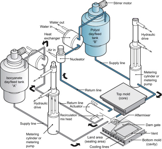
Applicable mold: resin mold (more than 100 pieces); ABS mould (more than 300 pieces); Aluminum alloy mould (more than 1000 pieces).
All tooling manufactured by Galaxy3DM is guaranteed for the life of the series production of the parts program.
Shrinkage
All shrinkage for the material systems are built into the tooling.
Dimensional Tolerances
These tolerances are based on a number of variables including, part density, mold temperature, mold alignment, injection rate, demolding time, component ratios, temperature, mold pressure and other production condition
All Thieme Corporation molding systems are close-loop systems which monitor all processing parameters to ensure quality.
Edge Gating
Always gate at the edge of the mold
Locate at the lowest point of the mold
Locate on a straight parting line section
Locate based on the lowest flow length of the material through the mold
Locate the gate on a less noticeable area or a non aesthetic area of the part
Locate the gate so the flow is parallel to designed in ribs
Mold Venting
Have vent locations at the highest point in the mold cavity
Maximize vents to assist in filling
Make vents wide and shallow not narrow and deep
Do not hesitate to send us 3D files for analyze of the ability to mold these RIM parts. We are ready to assist you in your RIM project.


86-13143415646
Contact:
 Tel: 86-755-23000620 Fax: 86-755-23000621
 Email:info@galaxy3dm.com/info@seetoptech.com
 Address: A3 , Dingfeng Industrial Zone, Fuyong Town, Shenzhen, China
Galaxy 3D Manfacturing Solution
Copyright (©) 2020 Shenzhen Seetop Technology Co.,Limited
